Virtual and Intelligent PCB Fabrication and Assembly Documentation

By Kevin Webb, Technical Marketing Engineer for the Valor Division of Mentor, A Siemens Business
Virtual machines today are used as a replacement for physical laptops or desktops to emulate computer systems for design and verification. For printed circuit board (PCB) design and manufacturing, some fabrication and assembly information such as artwork, drill, netlist, test, and component placement has been conveyed virtually to manufacturing for over 30 years. So how about articulating critical fabrication and assembly notes and drawings in an intelligent, electronic (a virtual) format?
The virtualization of fabrication and assembly documentation can be a powerful alternative to today’s non-intelligent static versions of PCB drawings and supporting specifications. All of the requisite manufacturing instructions would be conveyed as data elements to allow the recipient tool to automate the planning and execution of the manufacturing process preparation. This capability would streamline the process of new product introduction and, at the same time, increase overall efficiency.
The Road to PCB Data Virtualization
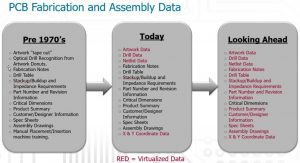
Before the 1970s, PCBs were designed by “hand-taping” components and traces using 4:1, red-and-blue, line vellum, and a precision camera then produced the 1:1 negative that became the manufacturing film. Drill information was conveyed via a drill tape. The artwork films and the drill tape were both physical formats. In the 1970s, Gerber Scientific introduced a machine-based format called RS-274-D that was supported by its vector photo plotters, which enabled the virtualization of PCB fabrication and assembly information. That was followed by the 274X format (Extended Gerber or X-Gerber), released as an enhancement to the RS-274-D format. The new format embedded the aperture information into each Gerber file, eliminating the need for separate and potentially “out-of-sync” aperture definition information. During this timeframe, the Excellon Automation Company designed a format to drive computer-numerical-control (CNC) drill and route machines.
Virtualization continued as specifications and formats were also developed to convey the PCB bill-of-materials, netlist, test and component placement information to manufacturing. More recently, standards such as ODB++ have combined all of the fabrication, bill-of-materials, netlist, test, and assembly information into a more intelligent XML-based format. However, during all of this time, a methodology to capture and a format to convey the critical fabrication and assembly documentation as intelligent data elements has been lacking.

Fig. 1: The PCB fabrication and assembly data roadmap, from the 1970’s to today, and beyond.
Virtualization’s Potential
Most engineers and designers would probably agree that the creation of fabrication and assembly documentation is one of the more time-consuming, tedious, and potentially error-prone aspects of the product development process. Many teams expend a significant amount of time and effort creating and maintaining automation to support the detailed notes and images required in fabrication and assembly drawings. Likewise, the various electronic CAD (ECAD) tool vendors expend a significant amount of time and effort developing functions to create and maintain items required to be included in the fabrication and assembly drawings, such as drill tables and pictorial representations of board stackups. The ECAD tool-vendor’s functions combined with the design teams automation helps ensure a certain level of accuracy and repeatability; however, this information is still non-intelligent and non-virtual. The single PCB or panel added to the drawing formats with notes, specifications, and dimensions conveys a static and potentially incorrect or incomplete representation of the manufacturing requirements.
Furthermore, even in the best-case scenario where all of the notes, drawings, and specifications are created correctly by the product development team, the non-intelligent information is still subject to potential misinterpretation or not even being understood at all by the fabrication or assembly vendor.
Capturing and Conveying Notes and Specifications
Even the most accurately designed PCB will not be fabricated or assembled correctly if the documentation does not accurately and completely convey all of the unique and specific manufacturing requirements. To mitigate this risk, a structure is required that not only supports the capture of existing virtualized data such as artwork, drill, and component placement, but also supports the translation of drawings and documentation from the PCB design into electronic format. The information documented in the drawing notes and specifications must be captured as intelligent metadata. At a minimum, this includes the capture and electronic representation of the following:
- Fabrication notes
- Drill table
- Stackup/buildup and impedance requirements
- Part number and revision information
- Product summary
- Customer/designer information
- Specification sheets
- Assembly drawings.
For a best case situation, critical dimensions should also be captured electronically.
Any system that supports a methodology to capture and a format to convey the above information as metadata should also ensure that the fabrication and assembly data would not have to be entered in its entirety for each design. Instead, templates based on design technologies could be established and applied to merge these requirements, along with board specific information, to create a comprehensive data set.
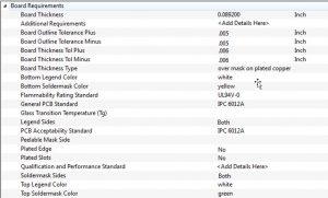
Here is an example for the board-level requirements: items such as board outline tolerances, board thickness and tolerances, silkscreen color, solder-mask color, flammability rating, PCB standards, and plating requirements would all need to be captured. The type of graphical user interface (GUI) that could be used to acquire this information and represent it as intelligent metadata is shown below.

Fig. 2: GUI example to show board-level requirements as intelligent metadata.
Along with board requirements, most aspects of the manufacturing process could and should also be captured such as smallest drill size, number of unique drill sizes, and the smallest trace. Likewise, most aspects of the assembly information should be represented in metadata such as test points, fiducials, number of components on each side, types of components, and quality-control information.
The underlying concept of this approach is to allow the recipient tool to automate the execution and planning of the manufacturing process preparation. For example, if the solder-mask, finish type, and color are defined electronically, the PCB fabricator could create a process through automation that would include material instructions based on the solder-mask settings. Similarly, if the use of buried discretes was defined electronically, the PCB fabricator could create a process through automation that would include routing instructions based on the designs settings.
Virtualization Benefits
Articulating the critical fabrication and assembly notes, specifications, and drawings in an intelligent electronic (virtual) format has multiple benefits, including:
- Eliminating the need to create labor intensive drawings and supporting documentation
- Providing the ability to share all of the necessary manufacturing instructions as electronic data
- Streamlining the process of new product introduction
- Increasing efficiency of both the supply chain and manufacturing
- Allowing the recipient tool to automate the execution and planning of the manufacturing process preparation.
These benefits are just the start of what can be realized. As design teams and manufacturing vendors become more familiar with the new intelligent non-static methodology, they will enhance their processes over time, resulting in improved timeliness, accuracy, and quality of the associated products that are developed using virtual documentation.
The Future Can Be Realized Now
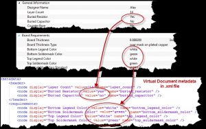
The ODB++ intelligent product model has been updated to now include a data model that conveys fabrication and assembly documentation which is fully inclusive within the industry standard ODB++ structure. The new data model provides a unique virtual documentation capability that seamlessly translates all data files, drawings and documents from PCB design in electronic form.

Fig. 3: The ODB++ intelligent model provides a unique virtual documentation capability that translates all PCB design data types and drawings into an electronic format.
As with any new technology, transformation to capture and generate data based on the updated ODB++ format will most likely occur in stages. Initially, design teams, ECAD tools, and manufacturers may just focus on just a few select areas that are the most critical, most subject to error, or most subject to misinterpretation. The goal for both the producers and the consumers of the data is to achieve the next level of communicating design intent to reduce potential confusion and improve automation. In the end, virtual documentation is a win for both development and manufacturing that would improve reliability and reduce time to market.
Think about all the information that needs to be communicated to fabrication and assembly that is not part of the PCB definition. Isn’t it time to move to an intelligent electronic means to communicate what defines a PCB?
Kevin Webb holds the position of Technical Marketing Engineer for the Valor Division of Mentor, A Siemens Business. Webb is an electrical engineer with more than 35 years of experience in PCB design, design for manufacturing, and EDA tool management.


